TUF GATE Aluminum Stop Gates

TUF GATE Aluminum Stop Gates are widely used in wastewater treatment plant design. Designed for flow control with minimal seepage. The gates consist of 1/4″ aluminum plates reinforced with aluminum structural shapes. The gates can be designed in-house for most any width and head.
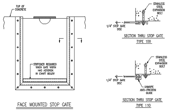
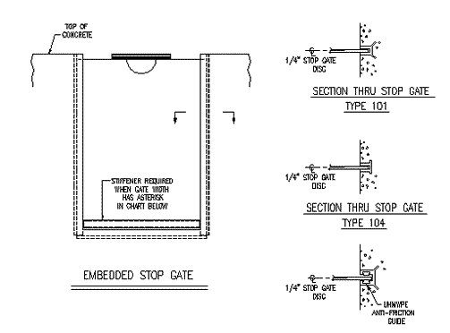
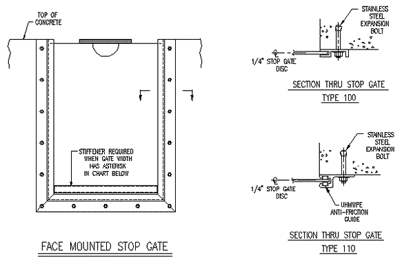
The frames are aluminum extrusions, alloy 6063-T6 and incorporate a continuous concrete anchor. Embedded as well as face mounted frames are available. Anti-friction inserts are an option for each frame type. The inserts serve to reduce the required lifting capacity of the gates.
The frames are aluminum extrusions, alloy 6063-T6 and incorporate a continuous concrete anchor. Embedded as well as face mounted frames are available. Anti-friction inserts are an option for each frame type. The inserts serve to reduce the required lifting capacity of the gates.
Features
- 1/4″ aluminum plates and reinforcing of alloy 6061-T6
- Extruded aluminum guides alloy 6063-T6
- Lift handles
- Portion of aluminum in contact with concrete is painted with bitumastic​
Options
- Reinforced for most standard sizes
- Design calculations
- Anti-friction inserts of ultra-high molecular weight polyethylene (UHMWPE)

Drawings

Embedded Stop Gate

Face Mounted Stop Gate
Selection Guide
HEAD - 6 INCHES
|
WIDTH (Inches)
|
STRESS (kei)
|
DEFLECTION (Inches)
|
LIFT FORCE with UHMWPE
|
LIFT FORCE w/out UHMWPE
|
|
12
|
0.37
|
0.00
|
11.58
|
19.99
|
|
18
|
0.84
|
0.02
|
17.34
|
29.98
|
|
24
|
1.50
|
0.07
|
23.12
|
39.97
|
|
30 *
|
0.07
|
0.000
|
33.98
|
55.02
|
|
36 *
|
0.10
|
0.001
|
40.78
|
66.03
|
|
42 *
|
0.13
|
0.001
|
47.55
|
77.03
|
|
48 *
|
0.17
|
0.002
|
55.34
|
88.04
|
HEAD - 12 INCHES
WIDTH (Inches) |
STRESS (kei) |
DEFLECTION (Inches) |
LIFT FORCE with UHMWPE |
LIFT FORCE w/out UHMWPE |
12 |
0.75 |
0.01 |
14.37 |
48.07 |
18 |
1.68 |
0.05 |
21.55 |
72.10 |
24 |
0.09 |
0.000 |
32.79 |
100.18 |
30 * |
0.14 |
0.001 |
40.98 |
125.22 |
36 * |
0.19 |
0.002 |
49.18 |
150.27 |
42 * |
0.27 |
0.003 |
47.55 |
175.31 |
48 * |
0.35 |
0.005 |
54.34 |
200.38 |
HEAD - 18 INCHES
WIDTH (Inches) |
STRESS (kei) |
DEFLECTION (Inches) |
LIFT FORCE with UHMWPE |
LIFT FORCE w/out UHMWPE |
12 |
1.12 |
0.01 |
19.05 |
94.87 |
18 |
2.53 |
0.07 |
28.57 |
142.30 |
24 |
0.13 |
0.000 |
42.15 |
193.78 |
30 * |
0.20 |
0.001 |
52.88 |
242.22 |
36 * |
0.29 |
0.002 |
63.22 |
290.67 |
42 * |
0.40 |
0.004 |
73.78 |
339.11 |
48 * |
0.52 |
0.007 |
84.29 |
397.56 |
HEAD - 24 INCHES
WIDTH (Inches) |
STRESS (kei) |
DEFLECTION (Inches) |
LIFT FORCE with UHMWPE |
LIFT FORCE w/out UHMWPE |
12 |
1.50 |
0.02 |
25.80 |
180.39 |
18 |
3.37 |
0.09 |
38.40 |
240.58 |
24 |
0.17 |
0.001 |
55.25 |
324.82 |
30 * |
0.27 |
0.002 |
89.08 |
408.02 |
36 * |
0.39 |
0.003 |
82.88 |
487.23 |
42 * |
0.53 |
0.008 |
98.89 |
588.43 |
48 * |
0.69 |
0.010 |
110.50 |
649.64 |
Specifications
1) Stop Gate Guides are to be extruded aluminum, alloy 6063-T6 or 6061-T6. If required, the stop gate frames shall incorporate an anti-friction UHMW insert to reduce the coefficient of friction to 0.2 or less.
2) Stop Gate Disc shall be a minimum of .25″ thick aluminum plate, alloy 6061-T6. The disc shall incorporate a lift handle for hand operation. The disc shall be stiffened as required to meet the loading requirements of the intended application with a minimum of deflection. Design calculations shall be furnished upon request.
3) Surfaces in contact with concrete shall be protected with a shop coat of bitumastic paint.
4) Aluminum Stop Gates shall be “TUF GATE“ as manufactured by Thompson Fabricating, LLC (B’ham., AL.) or approved equal.
